

The Basics of Current Transformers
Current Transformers (CTs) can be used for monitoring current or for transforming primary current into reduced secondary current used for meters, relays, control equipment and other instruments. CTs that transform current isolate the high voltage primary, permit grounding of the secondary, and step-down the magnitude of the measured current to a standard value that can be safely handled by the instrument. To determine which CT is appropriate for a particular application, it is important to understand the following characteristics that are used to classify current transformers.
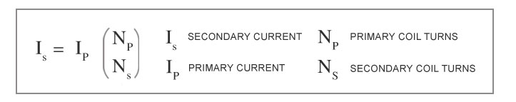
Current Ratio: Also known as the Turns Ratio (in general standings) is the ratio of the primary current to the secondary current. This value is perceptibly equal to the ratio of number of turns in the primary and secondary coils. The current ratio of a CT is usually high. The secondary current ratings are typically 5A, 1A and 0.1A. The equivalent current primary ratings vary from 10A to 3000A or more.
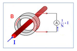
For example, an Ip / 5A ratio Current Transformer will deliver a secondary current (Is) of 0-5A which is proportional to the current measured at the primary (Ip). In the situation of 100/5 CT, the primary current is 20 times greater than the secondary current so when 100 amps are flowing in the primary conductor, it will result in 5 amps flowing in the secondary winding.
However, it is important to note that 100/5 rating and 20/1 rating of Current Transformers are not the same, even though their current ratios are equal. These rating numbers actually signify the complete values of “input/output current rating”.
Polarity: The polarity of a CT is resolute by the direction of coil winding around the core of the CT (clockwise or counter-clockwise). All current transformers have subtractive polarity. Maintaining proper polarity is important when installing and connecting current transformers to power metering and protective relays.
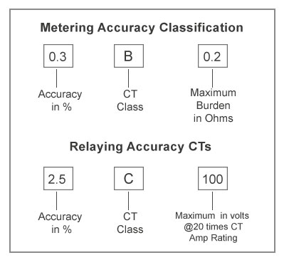
Accuracy Class: Accuracy Class describes the performance features of a Current Transformer and the maximum burden that can be allowed on its secondary circuit. Depending on their Accuracy Class, Current Transformers are classified for Metering Accuracy or Relaying Accuracy (Protection CTs). A CT can have ratings for both groups.
Metering Accuracy CTs are rated for specified normal burdens and designed to be highly accurate from very low current to the maximum current rating of the CT. Because of their high grade of accuracy, these CTs are typically used by utility companies for measuring usage for billing purposes.
Relaying Accuracy CTs are not as accurate as Metering Accuracy CTs. They are designed to perform with a reasonable degree of accuracy over a wider range of current. These CTs are typically used for supplying current to protective relays. The wider range of current allows the protective relay to operate at different fault levels.
How to select the right Current Transformers?
The following parameters that must be evaluated before selection of the proper Current Transformer for an application are:
- Accuracy Class Rating
- Rated load on Secondary side
- The voltage of the circuit
- Rated Secondary current
- Rated primary current
The choice must also consider the conductor profile and the maximum strength of the primary circuit.
Applications of Current Transformers:
The two main application areas of Current Transformers are current measurement and protection. They are also used for isolation between high voltage power circuits and measuring instruments.It is recommended to apply current transformers for currents of 40A or higher.
CT in Measurement – A metering Current Transformer is designed to measure current on a continuous basis. They work with a high degree of accuracy but within the rated current range. Current transformers have a primary winding to which the current to be measured is nourished. Measuring instruments are connected to a secondary winding. This allows them to be used in combination with Simple energy meters to power quality meters such as:
- Multifunction Energy Meters
- Kilowatt-hour meters (Basic Energy Meters)
- Power Factor Controller Relays
- Power Quality Analyzer
Why need Current Transformers to be installed?
- Electrical Control Panel (VCB, AMF, APFC, MCC, PCC, and Relay panels) and Drives.
- For commercial metering.
- For control in high-voltage electrical sub-stations and the electrical grid.
- To activate the protective relay in case of a fault current and isolate a part of or the full system from the main supply.
- Current sensing, recording, monitoring, and control.
- Standard CT for Laboratory purposes.
- Earth fault Protection/Differential Protection/Bus–bar protection system.
- Bushing type, oil-immersed CT in Power transformer.
TRINITY OFFERS FOLLOWING TYPES OF CT FOR ALL UPSTAIRS APPLICATIONS:
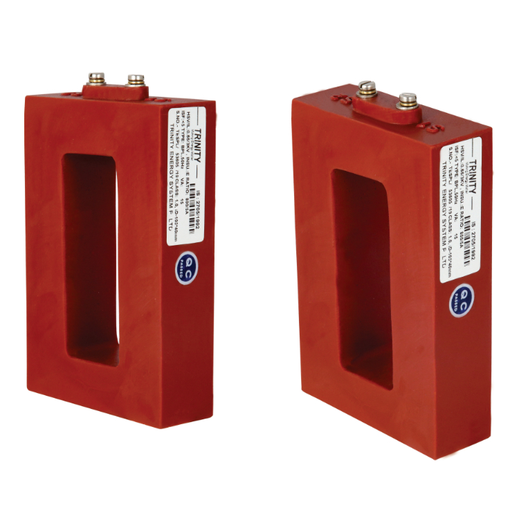
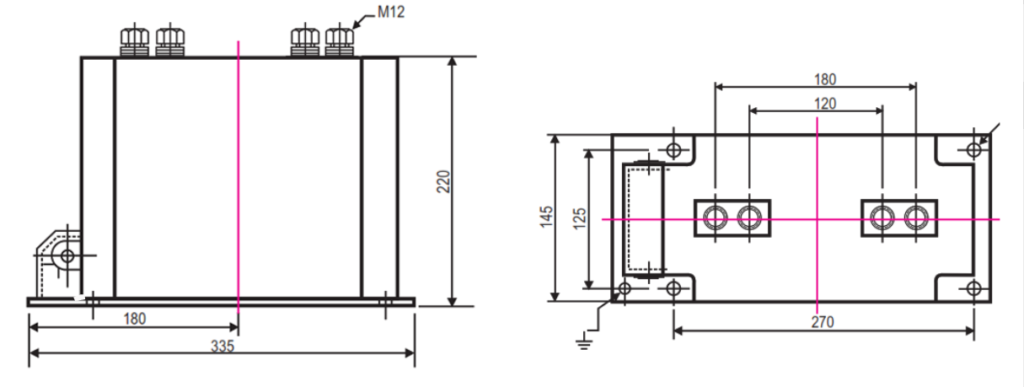
HIGH TENSION CURRENT TRANSFORMERS: SINGLE PHASE 11KV:
- Epoxy resin cast insulated upto 3 cores.
- The alternative combinations of rated primary current/secondary current 5A or 1A rated short-time core data are available on request.
LOW TENSION CURRENT TRANSFORMERS:
Bar primary Low Tension Tap Insulated CT type BPL
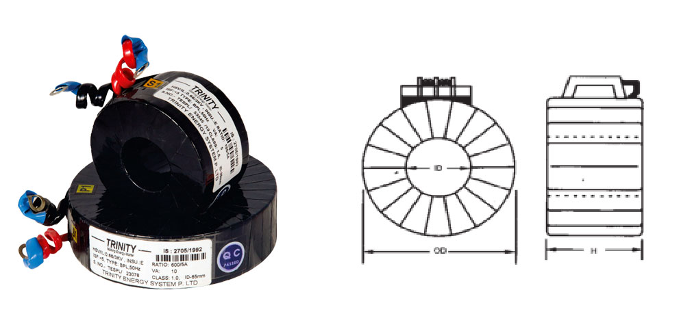
- CT available in standard secondary rating 5A/1A.
- Accuracy class 1.0, 0.5, 0.5s.
- C.T. available in busbar type also.
- Confirming IS: 2705/1992
- Other query on request.
Wound Primary Low Tension Current Transformer (LTCT):