

UNDERSTANDING TRUE POWER FACTOR:
Power Factor is one of the major elements that controls Power Quality. Power Factor Correction (PFC) targets to improve power factor which in turn controls the power quality, utilising capacitors to offset usually inductive loads. The non-linear loads in the increased complex networks adds a significant amount of burden to the network. PFC systems increase the efficiency of power supply, controlling the immediate cost-effectiveness.

POWER FACTOR CORRECTION: an overlooked but powerful for delivering energy efficiency and cost savings.
WHAT IS POWER FACTOR CORRECTION
From quite some time, power factor correction (PFC) techniques have been used widely to improve power efficiencies. Since Lead PF was considered as unity earlier, consumers added higher rating of fixed capacitors to maintain lead PF. This resulted in to problems of higher voltage in distribution network and harmonics due to capacitive circuit. Moreover, higher rating of capacitors installed are capital as well as revenue monetary loss to the customer and also can compromise safety. Cost savings are primarily achieved by diminishing PF penalties. Electric utilities promote energy efficiency to reduce their system losses. PF improvement frees capacity on the electrical distribution system, increases voltage levels, and decreases demand on transformers.
POWER FACTOR BASICS:
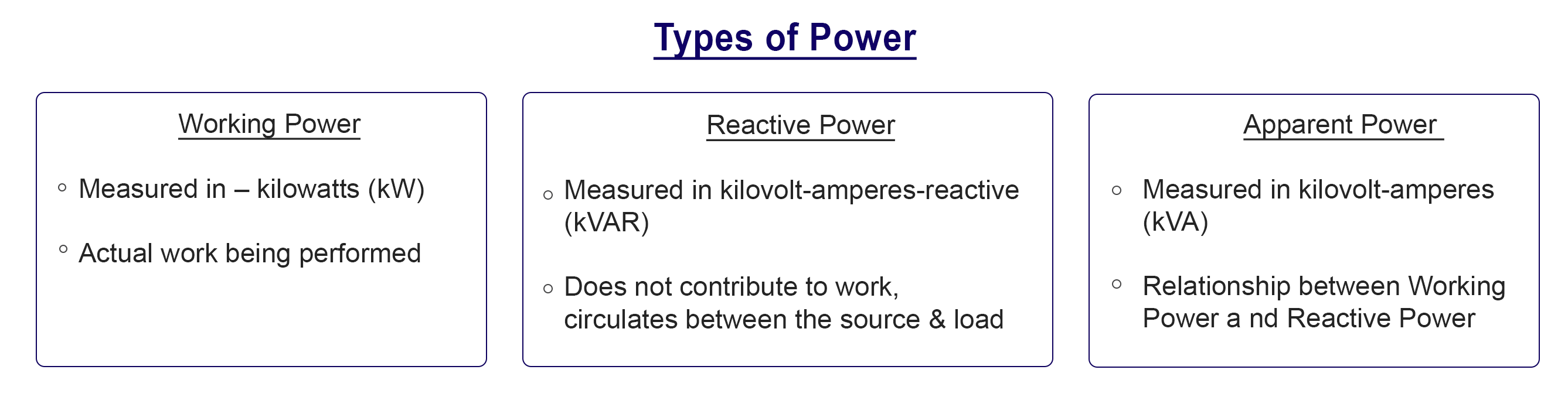
Power Factor can be expressed as Working Power/ apparent Power
PF=kW/KVA
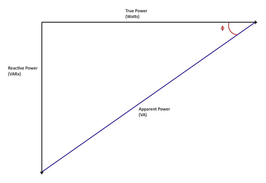
As, the diagram demonstrates, power factor is a comparison between the real power being
consumed to the apparent power or the demand of the load. Power factor penalties can be
avoided by correcting Power Factor.
Poor Power Factor:
- Inefficient usage of power
- Heat damage to insulation and other circuit components
- Reduction in the amount of available useful power
- Required increase in conductor and equipment sizes
IMPROVING POWER FACTOR
In a linear load, PF arises with the existence of a phase angle (ϕ) between the instantaneous current and voltage. An inductive circuit causes current to lag voltage, while a capacitive circuit causes current to lead voltage. PFC capacitors can mitigate the low PF caused by inductive loads.
HARMONIC DISTORTION
Harmonics is a term, used to describe the shape or characteristic of a voltage or current waveform, with respect to the fundamental frequency in an electrical distribution system. These are sinusoidal voltages or currents having frequencies that are integer multiples of the supply frequency (fundamental frequency). Harmonic distortion is a kind of pollution in the electrical supply. It can be produced by over saturating the magnetic core of a transformer or by the switching action of switch mode power supply (SMPS), or by a variable frequency drive (VFD). The distortion can contribute to many problems within a power network.
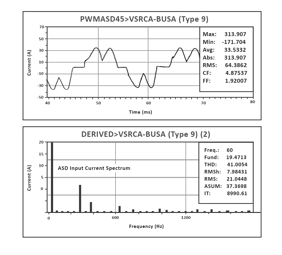
Example: tripped breakers, blown fuses, excessive heat, and degradation to power equipment. In Non-linear loads, Total Harmonic Distortion is used to measure the effective value of harmonic distortion. The following figure illustrates the waveform and harmonic spectrum for a typical adjustable speed-drive (ASD) input current.
HARMONIC EFFECTS OF PFC CAPACITORS
Harmonic resonance is a power quality issue that is difficult to visualize as the damages caused due to resonance would have brought the system out of resonance (self-correcting) by the time the engineer is performing measurement or analysis. Hence the important steps in diagnosing harmonic resonance is to first identify if the system configuration can drift into series or parallel resonance condition. A detailed computer-based harmonic analysis can usually identify the resonance condition. PFC capacitors are often selected to obtain the maximum cost savings. Doing so can amplify harmonics. The model below assumes the total reactive load as inductive and harmonic sources are viewed as current sources. Typically, it is difficult to fully characterize this model, as the load composition is often not available, and in any case varies over time. It is good to note the parallel installation of the PFC capacitor and how it affects the circuit.
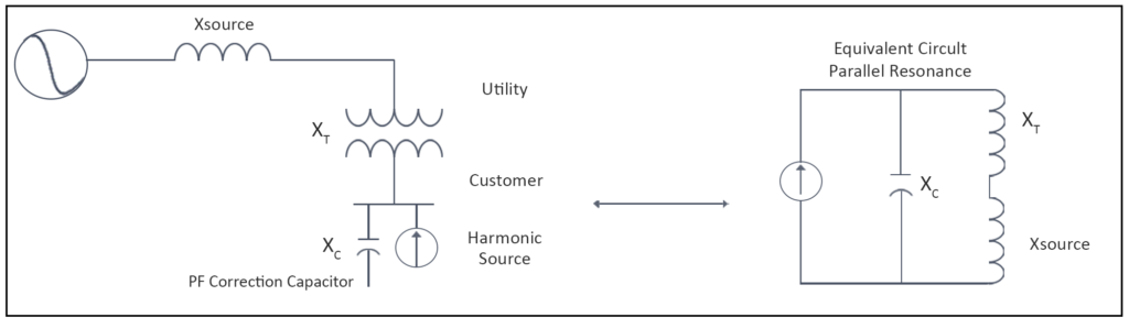
RESONANCE WITH SYSTEM IMPEDANCE
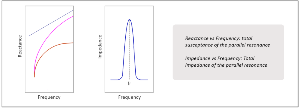
A PFC capacitor applied to the system impedance can resonate with the power network elements. Circuit resonance presents itself at a frequency where the capacitive reactance reach equilibrium with the supply impedance, such that current and voltage phasors are in line. There will always exist a frequency where PFC capacitors contain a parallel resonance with the load and system inductance.
OVERLOADING PFC CAPACITORS
Capacitors can be installed at several points in the electrical system and will improve the power factor between the point of application and the power source. However, the power factor and the increased current draw between the load and the capacitor will remain unchanged. Capacitors are usually added at each piece of offending equipment, ahead of groups of motors (ahead of motor control centers or distribution panels) or at main services. The application of capacitors depends on where the capacitors are to be connected, type of mounting, enclosure, voltage, etc. a system’s impedance is generally considered inductive. Therefore, as harmonics move beyond the fundamental frequency, more current circulates through the PFC capacitors. The absorbed reactive current can exceed the capacitor’s maximum current tolerance, causing premature failure and blown fuses.
OVERCOMING RESONANCE
To reduce the effect of harmonics, the systems natural impedance can be utilized. Simply placing the capacitor at a location within the system that does not cause parallel resonance with the supply can often reduce the effect. Resonant frequency varies with kVAR rating of PFC capacitor. Adjusting the kVAR rating can shift the resonance point away from a harmonic generating device.
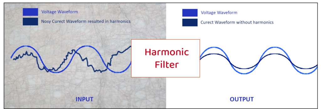
HARMONIC FILTERING
A harmonic filter is a device that reduces, or diminishes, harmonics to acceptable levels. They are commonly used to lower harmonic distortion to the levels detailed in IEEE 519, the IEEE Recommended Practice and Requirements for Harmonic Control in Electrical Power Systems.
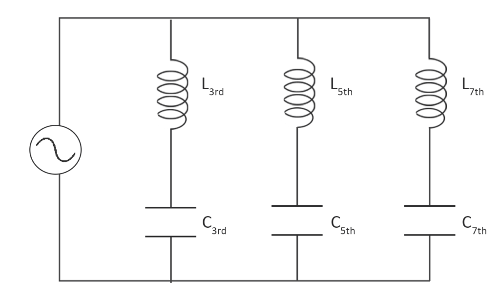
The combined capacitive and reactor circuit should exhibit an inductive behavior at critical frequencies while
exhibiting a capacitive behavior at the fundamental frequency. Tuning the filter should be performed at the lowest order harmonic frequency. This is found at the 5th harmonic, but this will vary depending on the magnitude and frequency of the present harmonics. If multiple harmonics are present in the system, it is possible lower harmonics will be amplified. For example, a 7th order harmonic filter will magnify harmonics near the 5th harmonic. Therefore, it is often necessary to deploy multiple filters at each specific harmonic.
CONCLUSION
Before making any changes to the Network, it is of utmost importance to thoroughly go through the behavior of PFC capacitors along with their effect on PF and harmonics. A regular survey of harmonics is useful to determine existing levels and conclude if filtering is required. Scrutinizing near the PFC for harmonic level should be performed timely to see its effect on the circuit. Maintaining these records are essential for analysis to verify that a PFC is not creating more issues than it tends to resolve.
TRINITY ENERGY SYSTEMS